If you are on this page then we will assume that you have already purchased the parts for your computer build. If you have not done so yet, click on the PC BUILDS button in the navigation bar and select the type of build you want to proceed with and order your parts from the provided links. The buttons will link you to the best available price from the most reputable vendors.
These simple instructions will make it easy for you to transform your valuable pile of parts into a powerful new computer. The assembly instructions here are quite universal no matter which build or parts you decide to use. It is always best to consult any manufacturer installation guides or user manuals if you have specific questions about your parts but it is likely that you will be able to complete the project with little reference to the manuals.
ASSEMBLY GUIDE
Page 1
1. PREPARE YOUR WORKSPACE
You will need a sturdy table and plenty of light because you will be working with some small parts inside your computer case. Choose a location that is not carpeted if possible. Your kitchen tables or a clean workbench in the garage are a good location. The metal parts you will be assembling have the potential to scratch the surface of your workspace so it is advisable to put something down beneath your computer such as newspaper. A small bowl or other container is a great place to store your screws and other small hardware so you do not lose them.
The only tools you will need are a phillips screwdriver (preferably magnetized), a standard screwdriver, and an anti-static wristband (optional). Static electricity is your enemy so be sure to ground yourself before touching parts! If you are working without an anti-static wristband then touch a metallic object such as the unpainted inside of the computer case.
Many of the circuit boards and computer chips in your computer are very sensitive to static electricity. Even a small surge or spark can ruin your RAM memory, CPU chip, motherboard or video card. The anti-static wristband will help eliminate much of the risk, but you must still take some easy precautions to further reduce the odds of zapping a component. If you don't have a wristband then you will have to take extra precautions. The following are some extra precautions you can take to keep your parts safe:
• Keep the components in the protective anti-static sleeves until you are ready to install them.
• Don't rub your hands on your clothes when handling the components.
• Don't touch the components without first grounding yourself by touching the unpainted metal of the computer case.
• Don't shuffle your feet on the carpet, especially if you are wearing only socks or slippers.
• Put the anti-static wristband on your wrist and attach the other end to either the center screw of a grounded wall outlet or clip it onto an unpainted metal portion of the computer case. This will cause any static you generate to be transferred away from your body before it can harm your components.
2. PREPARING THE COMPUTER CASE
Your case will likely look a little different, but you will be able to use these instructions no matter what case you have. Remove the case from the box and lay it on its side so that the back of the case is on your left and the front of the case is on your right. The left side panel should then be facing up toward the ceiling. Next you will remove the two screws on the back that hold the left side panel (which is now on top) in place. Now you can remove the side panel to expose the inside of the case.
Now when you look down into the case you should see something similar to the picture above. The big open area is where the motherboard will be installed. The space in the lower left corner is for the power supply (PSU). The 5.25 inch bays in the upper right are for CD/DVD and Blu Ray drives. The 3.5 inch bays on the lower right are for hard drives. The remaining components will be installed on the motherboard itself. There are some wires on the right that will be plugged into the motherboard to power the case fans, LED lights and switches on the front of the computer.
If your case did not come with the fans attached you will need to attach them yourself. The most important one attaches to the inside of the rear panel to blow air out of the back as shown in the picture above. There is another one that goes in the front of the computer near the bottom. You may have to remove the front panel in order to attach this fan, but it should already be installed when you receive the case. The fans attach simply by placing them against the side of the case, lining up the holes and inserting the screws. If you ordered extra fans there are several vents on the sides designed for attaching fans. The best place to attach an extra fan is in the middle of the left side panel (the one you just removed) so that air is blowing in on the video card and CPU chip.
Fans are critically important to your computer because they keep the air inside the case cool. Heat is the enemy of your computer, especially the CPU chip and the video card. Many of the components in your computer generate heat. Without good air flow the temperature will quickly rise and your critical components will overheat, which can ruin them.
All gaming computer cases offer excellent airflow with plenty of ventilation. This will serve to keep your computer cool and extend the life of your CPU chip, video card, motherboard and power supply. Now that you have prepared your workspace and opened up the computer case you are ready to begin installing your components!
3. HOW TO INSTALL THE POWER SUPPLY UNIT (PSU)
The power supply is the device that plugs into your home's wall outlet and powers the computer. Almost all of your computer's components will plug into the power supply to receive the proper amount and type of power.
Maneuver the power supply into the corner at the bottom left of the computer case. You will have to lower it into the case, then slide it to the left until it contacts the back of the case. When you look at the back of the case it should look similar to the picture above. Make sure the end with the fan ventilation and the on/off switch is exposed out the back side of the case. The wires should be inside the case facing the front.
The next step is to secure the power supply in place using the four screws. Align the holes in the case to the corresponding holes in the power supply. Make sure the voltage switch on the back of the power supply is set to 110/115 instead of 220/230 if you live in North America. On to the next and most important part!
4. HOW TO INSTALL THE MOTHERBOARD
The motherboard is a large circuit board loaded with microchips performing many vital functions. All of your computer's components fit on or are connected to the motherboard. You can use these instructions even if you are using a different motherboard than the one pictured. All current motherboards have essentially the same components and are labeled similarly. They may be arranged a bit differently depending on the brand, but these instructions will work for any motherboard you are installing.
Make sure you buy a motherboard that uses the same socket type as your CPU processor or else they will not be compatible with each other. If you selected one of the recommended builds on this site then you won't have any compatibility issues. Otherwise, make sure you have selected compatible parts before proceeding.
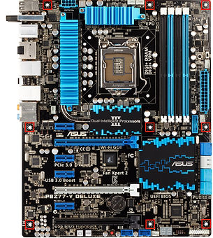
The pictures above give you a good look at a motherboard and its various features. We will be attaching components to most of the features pictured above, but for now the only thing we will be doing is attaching the motherboard to the case and connecting it to the power supply. By the time we are done assembling the computer you will be familiar with all the features shown above and know what everything is and what it does.
The picture above shows the I/O panel on the motherboard. I/O stands for Input/Output, which makes sense because this area contains all the jacks for plugging in your peripherals such as the keyboard, mouse, speakers, printer and ethernet cable for network access. Notice how the I/O panel juts out from the rest of the motherboard. This panel will actually poke out through the back of the computer case so the jacks will be accesible to you.
The picture above shows you the area of the case where the I/O panel will be positioned. First you will need to snap the metal I/O shield into place. The I/O shield is in the motherboard box. If there is already an I/O shield attached to the case in that space you will need to remove it with a flathead screwdriver and then attach the one that came with your motherboard.
Install the Motherboard Inside the Case
The next step is to attach the motherboard to the case. First, there are usually 9 screwholes in the motherboard. Look at the pictures above to see their standard locations. You need to line these holes up with the holes in the bottom of the case, then insert a tall brass mounting screw (also called riser screw or stand-off) into each hole in the case that aligns with a hole in the motherboard. Only insert mounting screws into aligning holes. The purpose of the mounting screws is to keep the motherboard from resting against the case and create a space between the case and motherboard. The best way to determine which holes align is to maneuver the motherboard into the case and insert the I/O panel into the I/O shield that is attached to the case. Remember to follow the static-prevention rules when handling the motherboard! Once the motherboard is in place you can more clearly see which holes align between the case and the motherboard. Make a mental note of which holes align, then remove the motherboard from the case. Insert a brass mounting screw into each aligning hole and tighten it. You may have to put the motherboard in and out a couple of times to ensure you get all the aligning holes correctly identified. Be very careful not to scrape the motherboard against the mounting screws or the case as you maneuver it.
The next thing to do is to place the motherboard into the case and onto the mounting screws. Then insert the screws from the motherboard box through the holes and into the mounting screws. It helps to use a magnetized phillips screwdriver. Be careful to avoid scraping or scratching the motherboard with the screws or the screwdriver. Tighten the screws firmly but don't tighten them too much or you may damage the board.
Attach the Cables to the Motherboard
It's important and helpful to note that each of the connectors is usually labeled directly on the motherboard in small lettering as to what that connector is for. If there is any doubt, always refer to the manual that came with your board.
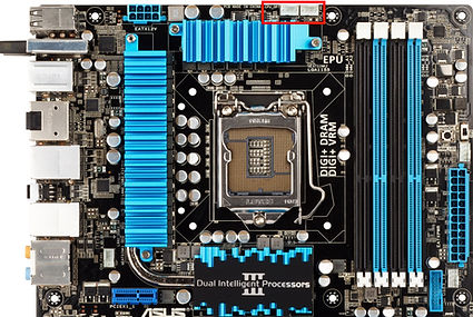
Now you can attach the 24-pin power cable from the power supply to the white ATX Power Connector on the right edge of the motherboard (refer to the picture above). This cable provides all the electricity in the proper voltage for the motherboard.
Next, you will want to connect the square 4-pin or 8-pin ATX power cable from the power supply to the square socket on the top edge on the left side of the motherboard (refer to the picture above).
See the group of small cables from the front of the case? Those cables are for the power button, reset button, warning speaker and various LED lights on the front of the case. To connect those use the rectangular front panel connector that came in the motherboard box (refer to motherboard manual for questions). Attach the cables to the front panel connector and then plug the connector into the white socket in the lower right corner of the motherboard (refer to the picture above).
If your case has a front panel USB port you can attach its cable to one of the blue sockets at the very bottom of the motherboard. The cable should be inserted so the missing pin on the cable aligns with the missing pin on the socket. If your case has a USB 3.0 port you can attach its cable to the blue USB 3.0 socket adjacent to the 24-pin ATX Power Connector.
If your case has a front panel IEEE 1394 (Firewire) port you can attach its cable to the 1394 socket on the motherboard. Note: Not all motherboards have a 1394 socket and connecting a 1394 port to a USB socket will likely damage your board so consult your motherboard's manual to see if you have a 1394 socket on your board. The cable should be inserted so the missing pin on the cable aligns with the missing pin on the socket.
If your case has a Sony/Philips Digital Interface (SPDIF) port you can attach its cable to the SPDIF socket on the motherboard. It is located along the bottom edge on the left-hand side of the board.
Make sure all the case fans are plugged in. You will need them to keep the air inside the case cool. Some fans have straight four-pin plugs that attach to cables from the power supply. Other fans have square four-pin plugs that attach to the small white sockets along the middle right edge of the motherboard on either side of the 24-pin ATX Power Connector and one on the middle left side of the board behind the I/O panel. Now your motherboard is securely fixed in place and you are ready to begin installing the components it houses!
5. HOW TO INSTALL THE CENTRAL PROCESSING UNIT (CPU)
The processor (also called a CPU - Central Processing Unit) is the brain of your computer. It performs complex calculations, makes logical decisions, executes computer programs and sends instructions to the rest of the computer.
CPUs made by Intel and AMD are physically different, so I have included separate instructions for each.
How to Install an AMD CPU
Your processor should look similar to the picture above. Remember to follow the anti-static precautions when handling it!
Before installing your processor, you may want to consult the user manual that came with your motherboard for additional instructions.
You will be installing the processor into the white square that looks like the one pictured above. First, you will need to raise the metal arm lever on the side of the square by lifting up on the unattached end. Notice that two of the socket's corners do not have holes. Now look at the underside of the processor chip and you will see that two of the corners do not have pins. Turn the processor chip over so the pins face down. Align the two corners without pins to correspond with the two corners of the socket without holes. You should now be able to gently insert the chip into the socket. Do not push or force it. The chip should just drop into place without any effort. Check to confirm the chip is evenly inserted into the socket all around without any gaps. Now you can gently lower the lever arm to lock the processor chip into the socket.
How to Install an Intel CPU
Your processor should look similar to the picture above. Remember to follow the anti-static precautions when handling it!
You will be installing the CPU in the socket connector as shown in the picture. If the motherboard has a plastic cover on the socket you will need to remove that first. To open the socket you must unclip the handle on the side of the socket and raise it up. Now you can lift up the main cage to expose the socket. Do not touch the pins!
Place the processor over the socket such that the notches line up. There is also an arrow on the processor that lines up with the corner of the socket with diagonal pins. Once the CPU chip is lined up properly you can lower it into place, close the cage and clip the retaining handle down. This should take only a little force. If you encounter too much resistance you can double-check to make sure you inserted the processor chip correctly. Refer to your user manual if you are uncertain about any step in this procedure.
6. HOW TO INSTALL THE CPU HEAT SINK FAN
When your computer is running, the CPU processor will get very hot, very fast and will overheat if not properly cooled. A heat sink works like the radiator in your car to pull heat away from the CPU chip. The heat sink is made of aluminum, copper or another metal that conducts heat well. It is composed of many fins that transfer heat to the air being blown across them by the attached fan. The warm air is then pulled out of the motherboard compartment by the case fans. Good air flow inside your case is important to keeping internal components such as the CPU at an optimal operating temperature.
Heat sinks come in many different styles. Above are a couple examples including a stock heat sink provided with an Intel processor as well as an aftermarket one that provides more effective cooling. If your CPU came with a heatsink fan you do not have to buy one seperately unless you plan to do any overclocking. Overclocking will push your CPU to higher than normal temperatures and more efficient cooling from an aftermarket heat sink is highly recommended.
It is a good idea to refer to your motherboard user manual before installing the stock heat sink fan. It is not really difficult, but if you don't do it right you could potentially damage the CPU chip. For this reason you should use extra caution when installing the heat sink.
To improve the transfer of heat away from the CPU and into the heat sink you need to apply some thermal compound. This is a compound that ensures there are no gaps or air bubbles between the CPU chip and the heat sink and will guarantee excellent heat transfer and optimal cooling of the processor. Some heat sinks come with the thermal compound already applied, but most of the time you will have to apply it yourself.
The first thing to do is to determine if your heatsink comes with the thermal compound pre-applied. Check the installation manual that came in the box if you have one. Look at the bottom of the heat sink. If there is a piece of film or tape it should have writing telling you that thermal compound is present. If yours does not say this then you will have to assume it does not have thermal compound pre-applied.
If your heat sink does not have thermal compound pre-applied, remove any film or tape on the bottom of the heat sink. If the bottom is not perfectly clean and smooth just gently wipe it with a lint-free cloth. Now open the tube of thermal paste and apply a small amount to the raised center surface of the CPU chip. Spread it evenly by very gently using the edge of an old credit card or stiff piece of paper. Only a very thin layer is needed. Putting too much thermal paste between the CPU and the heat sink will actually inhibit the transfer of heat away from your CPU so use a very thin layer.
If your heat sink has a stepped edge along one side make sure that edge is facing the raised section of the CPU Socket Connector. Place the heat sink on top of the processor chip so it makes even contact all around - do not tilt it. Do not push on the heat sink or apply pressure that could damage the CPU chip. Once it is properly positioned you can attach the clip on one side to the plastic tab of the socket connector. Aftermarket heat sinks usually have special mounting brackets so refer to your heat sink user manual when installing an aftermarket heat sink. Do not apply pressure to the heat sink itself, only apply pressure to the clip. This step can be a little tricky so be patient and don't rush it.
Once you the heat sink is securely seated, double check that it is level and evenly in contact with the processor chip all the way around. Make sure it is not loose or caught on the raised portion of the socket connector. Now you can connect the fan's power cable to the corresponding jack on the motherboard, which is usually at the top of the motherboard similar to the picture above.
Believe it or not that was the hardest part of assembling your computer! The rest will be easy.